
How to Create a Drawing in SOLIDWORKS (2026 Guide)
SOLIDWORKS is a 3D CAD software, but there is still a place for 2D prints. This is often used for manufacturing validation and is an easy form of communication that has been involved in the industry for many years. This blog will walk you through how to create a 2D drawing from your 3D SOLIDWORKS models.
How to Start a New Drawing in SOLIDWORKS
When designing in SOLIDWORKS, you can create either parts, assemblies, or drawings. Drawings pull the 3D information and format it in a 2D format. The following steps can be used to create a new SOLIDWORKS drawing.
Open SOLIDWORKS
Select File > New
Alternatively, you can select the paper icon with the folded corner or press CTRL+N
Highlight ‘Drawing’
Select ‘OK’
Select the sheet size you would like when prompted and select ‘OK’ once again


How to Add a Model View in a SOLIDWORKS Drawing
Once you have a drawing created, you need to add the model views of the part or assembly you would like to create the drawing of. If you would like to follow along with the sample steps, you can download the sample model used in this guide (SOLIDWORKS 2023 and newer).
Select the Model View command from the Drawing tab of the CommandManager.
If your model is already open, double-click to select it in the PropertyManager. Otherwise, select the ‘Browse’ option and navigate to part and select ‘Open’.
If following along with the sample component, open browse for ‘Sample Block.sldprt’.
Click on your drawing sheet to place the front view.
Move your mouse above the front view you place and click once again to place a top projected view.
Move your mouse to the right of the initial front view you created and click again to create a right projected view.
Move your mouse to the top right corner of the initial front view you created and click again to place an isometric projected view.
Hit the Escape key to exit the command once all of your views have been placed.
If you ever would like to add more projected views, highlight the base view you would like to project from and select the ‘Projected View’ command from the Drawing tab of the CommandManager. You can then repeat steps 1-7.

Steps 1-2

Step 4
How to Annotate a SOLIDWORKS Drawing
Now that your drawing views have been placed, we’ll need to add annotations, such as dimensions. The annotations will be used to communicate the details of the design to the person reviewing the 2D documentation.
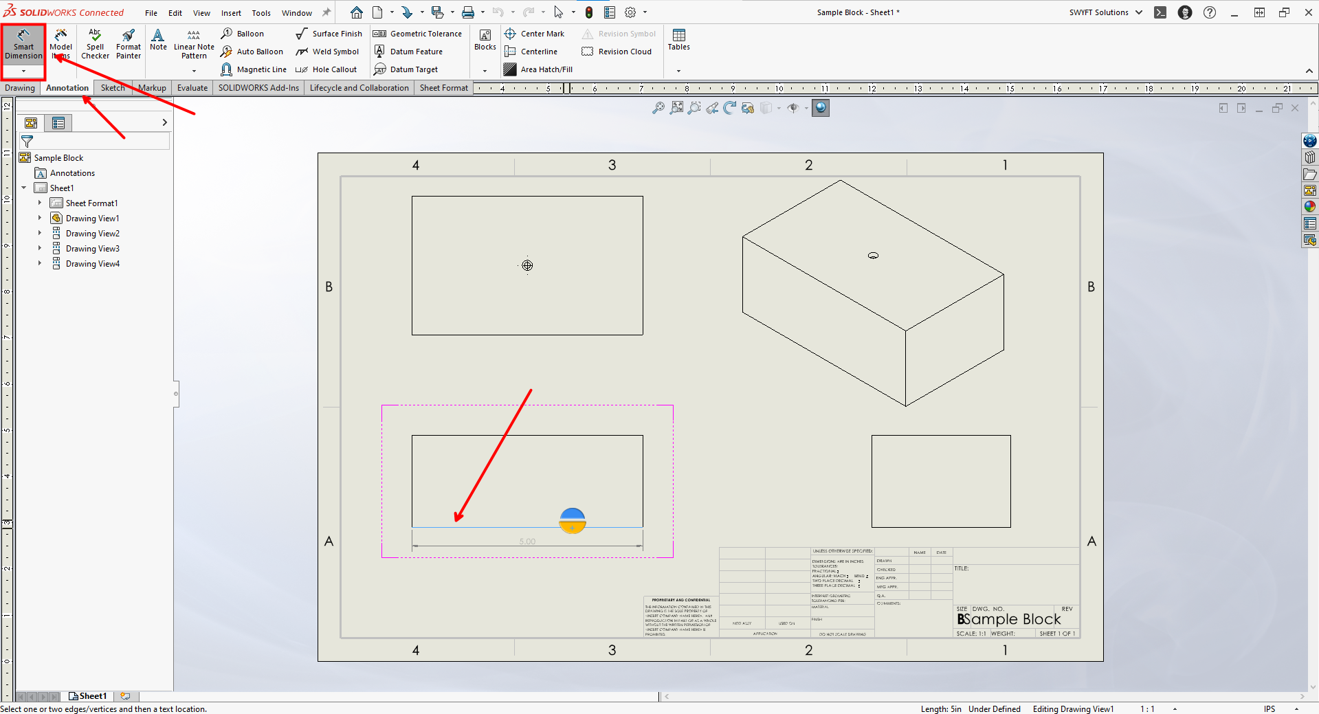
Select the ‘Smart Dimension’ command from the Annotation tab of the CommandManager.
Select an edge you would like to call out a dimension for and click off to the side of that edge to place the dimension.
Repeat step 2 for all edges you would like the dimension called out for.
If following along with the sample problem, make sure the height, length, and width of the block are all called out. You can also use the '‘Hole Callout’ command on the Annotation tab of the CommandManager to add details about the hole in the sample model.
Steps 1-2

Completed SOLIDWORKS drawing
Summary
3D CAD opens up a whole new world, but many processes are still dependent on 2D representations of 3D CAD data. SOLIDWORKS helps you streamline this process with easy drawing creation and quick annotations. This provides you with the ability to share the representation of the model as a PDF. As long as your drawing is fully defined, the end reader should be able to create a fully accurate representation of your part/assembly in 3D. If you are looking to accelerate your learning on SOLIDWORKS Drawings basics, be sure to check out the SOLIDWORKS Essentials training!
Matt is a Customer Success Manager at SWYFT Solutions and started using SOLIDWORKS while earning his Bachelor’s in Mechanical Engineering at Grand Valley State University and has been hooked ever since! He now specializes in 3DEXPERIENCE Works solutions, including 3DEXPERIENCE SOLIDWORKS. Outside of work, Matt loves to travel, hike, and discover new music.
Connect with Matt on LinkedIn