
How to Create a Part in SOLIDWORKS
SOLIDWORKS is a computer-aided design software, otherwise known as CAD. It specializes in 3D modeling, allowing you to bring your dreams to life! Whether you’re moving from 2D CAD or new to CAD altogether, SOLIDWORKS has a user-friendly interface and you’ll be up and running before you know it. Everyone has to start somewhere, and generally, that’s making what is known as a part. This blog will walk you through the basics of creating your first part in SOLIDWORKS.
How to Start a New Part in SOLIDWORKS
When designing in SOLIDWORKS, you can create either parts, assemblies, or drawings. Parts are the building blocks of assemblies and a drawing can create 2D representations of either parts or assemblies. The following steps can be used to create a new SOLIDWORKS part.
Open SOLIDWORKS
Select File > New
Alternatively, you can select the paper icon with the folded corner or press CTRL+N
Highlight ‘Part’
Select OK


How to Navigate the SOLIDWORKS User Interface
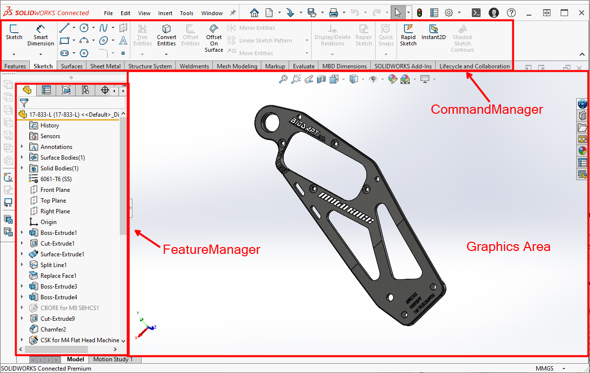
The SOLIDWORKS user interface is quite intuitive and is quite customizable. There are four main areas of concern when creating your first part.
Graphics Area - The main area in which you can see your 3D model
FeatureManager - The panel along the left side of your screen that will show a linear history of all of the features you’ve added to your model
PropertyManager - Another panel that appears in place of your FeatureManager along the left side of your screen when editing a feature
CommandManager - A panel along the top of your window with access to commonly used features and tools
Start with a 2D Sketch
Even though it’s 3D CAD, the foundation of a 3D part is still a 2D sketch. For this example, we’ll start with a very basic block as an example.
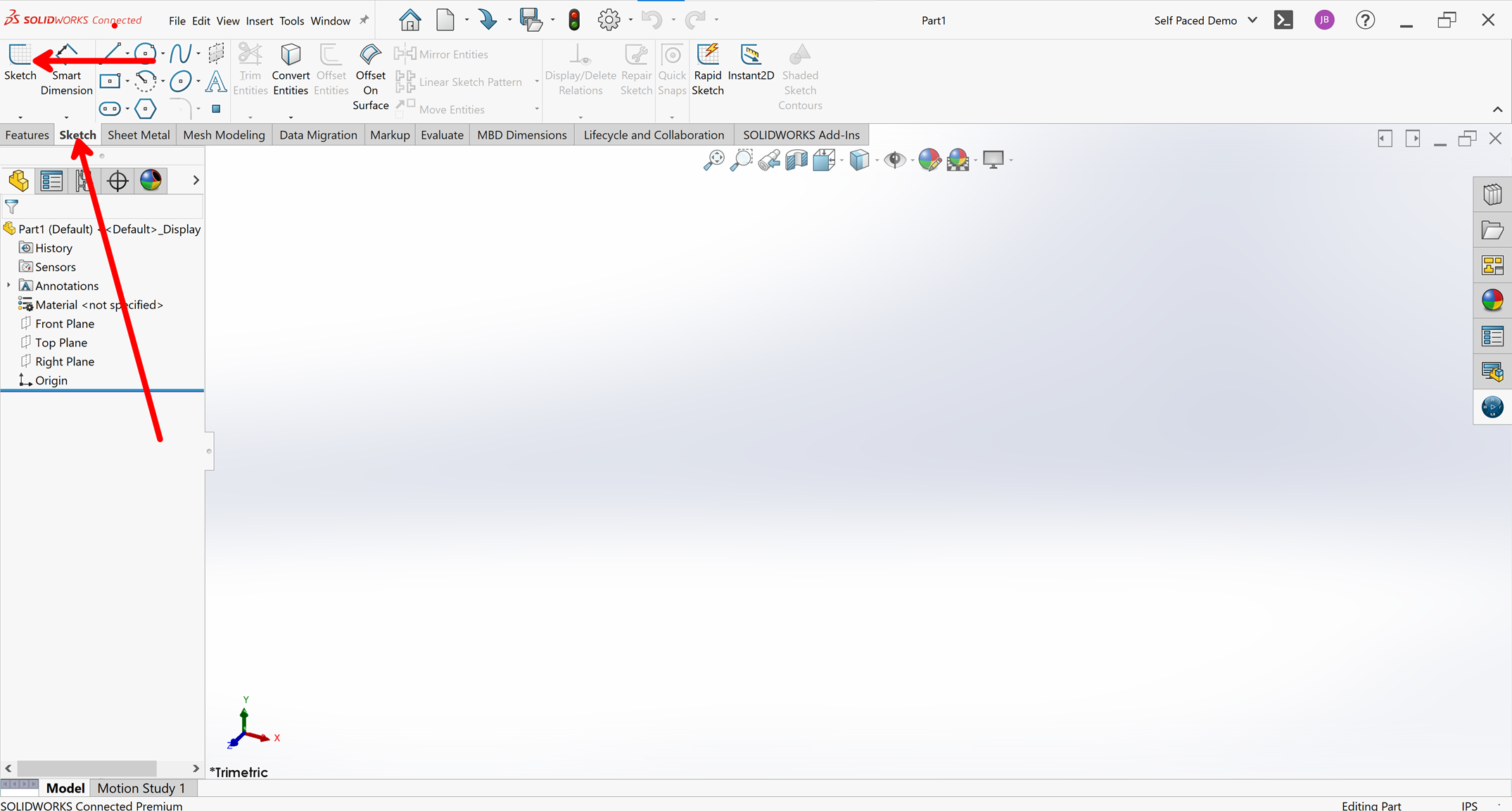
Navigate to the Sketch tab in the CommandManager and select the Sketch command.
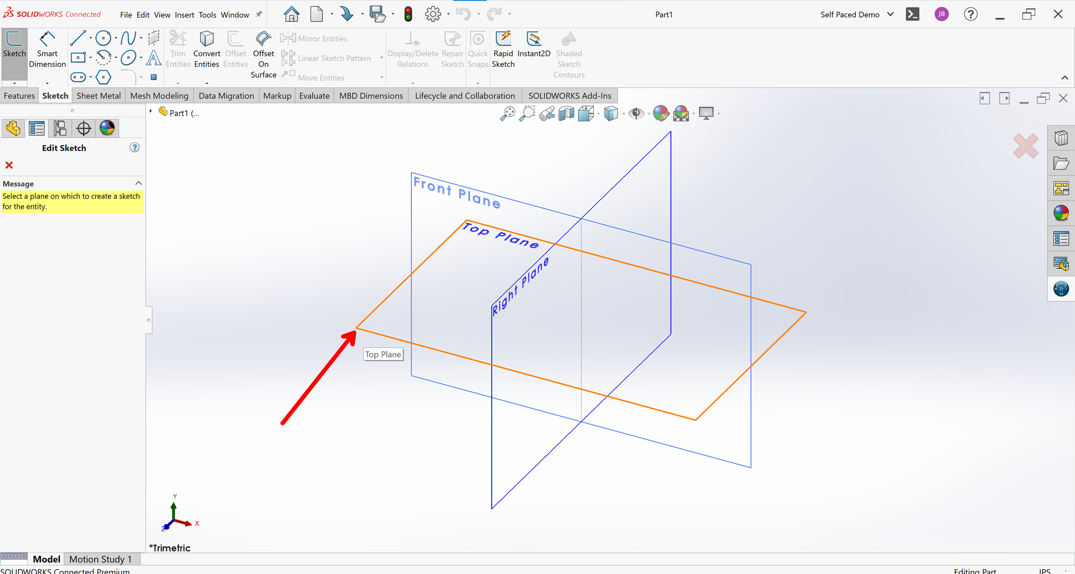
Select the plane you would like to sketch on. In this example, we’ll select the Top plane.
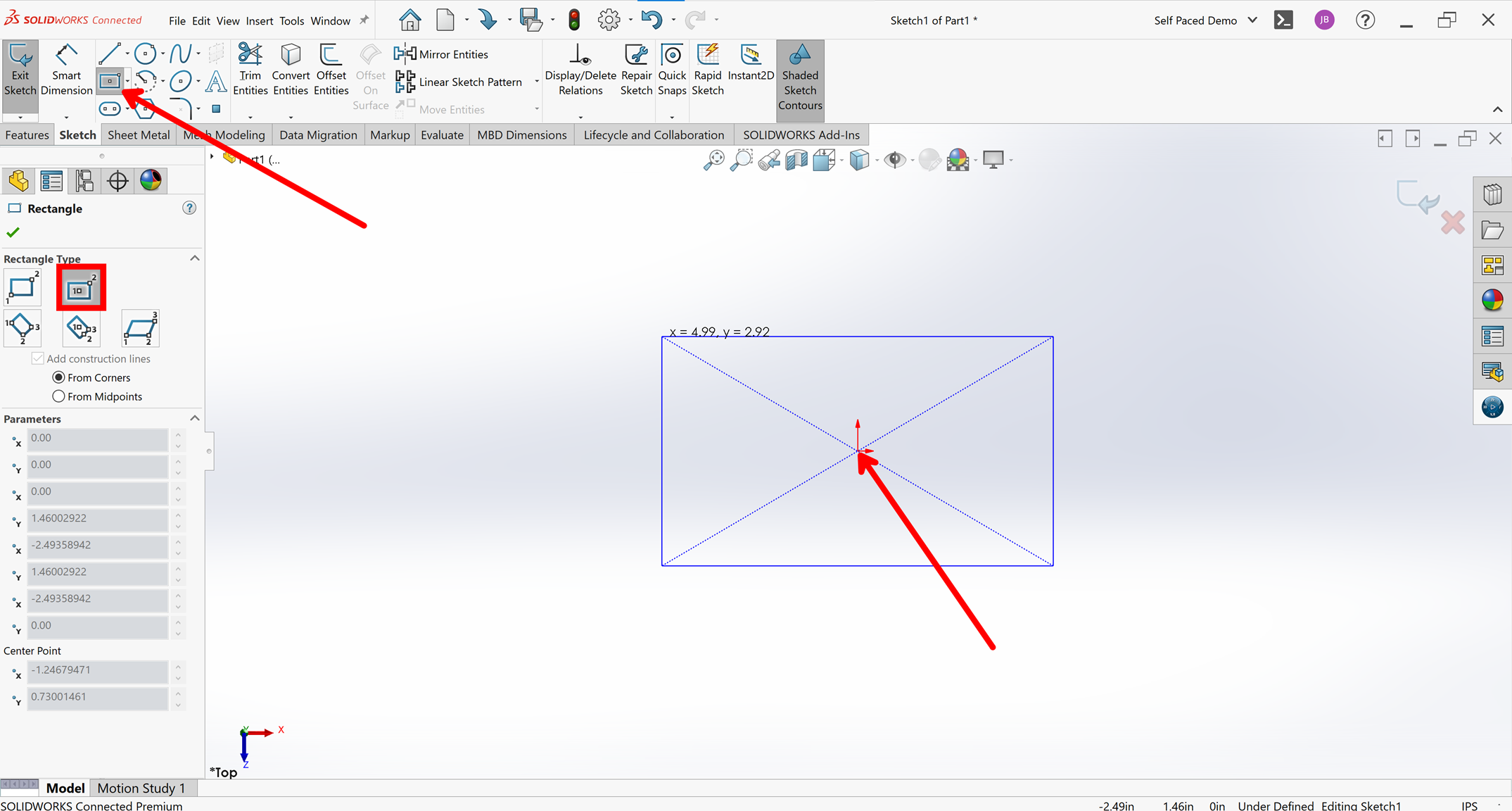
Select the Rectangle sketch command from the Sketch tab on the CommandManager and confirm the Center Rectangle is selected in the PropertyManager along the left side of your window.
Click once on the origin (red arrows in the graphics area) and move your mouse outwards. You will see a rectangle form. Click once more to place the outer corner of the rectangle.
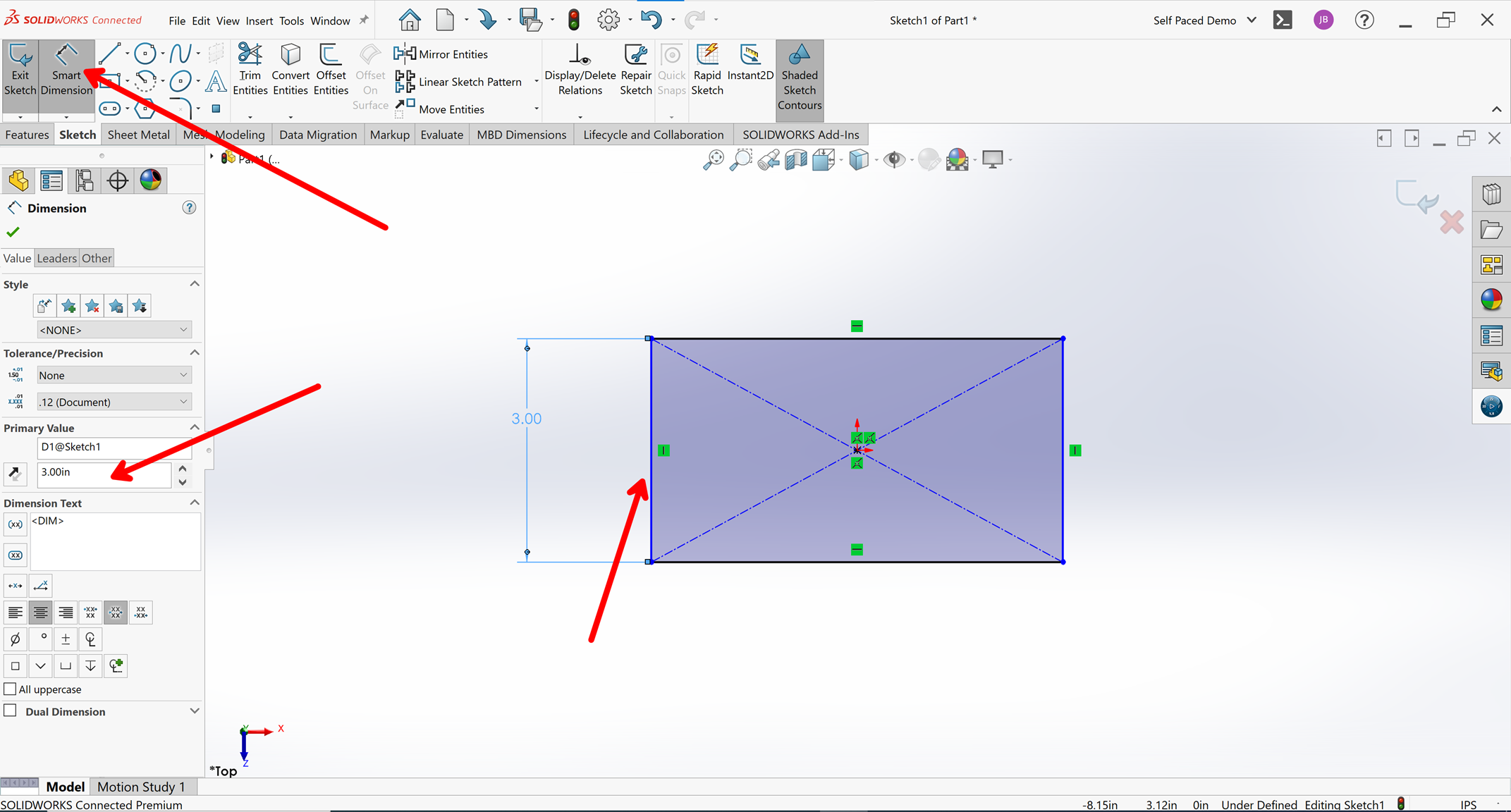
Activate the Smart Dimension command from the sketch tab of the CommandManager.
Click on the left edge of the rectangle sketch. Move your mouse outwards, and click once more to place the dimension.
Type a value of ‘3in’ and hit ‘Enter’ to confirm.
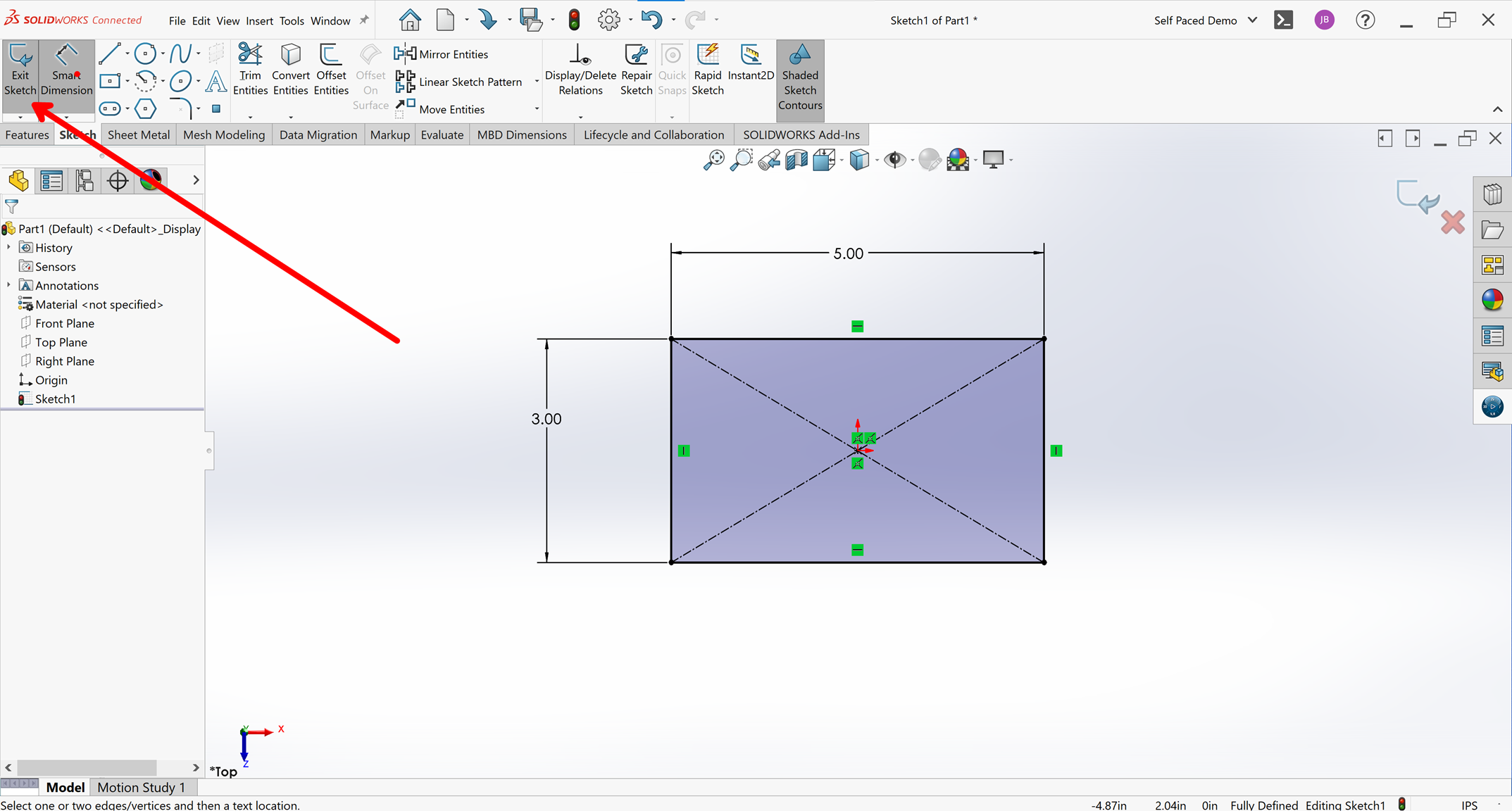
Repeat steps 8 and 9 for the top edge of the rectangle and set its dimension to ‘5in’.
Notice how the sketch lines turn black. This means that it is fully defined. It is good practice to have all sketches fully defined.
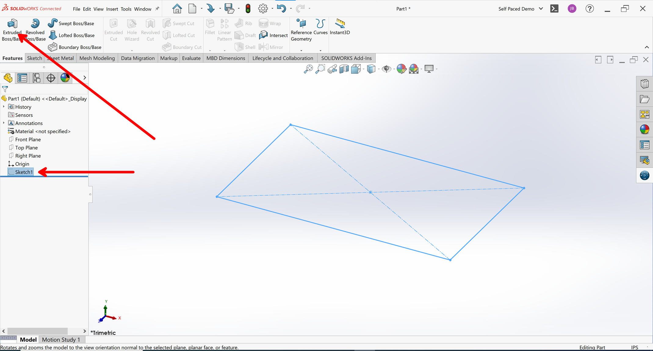
Select the ‘Exit Sketch’ command on the CommandManager Sketch tab.
Navigate to the CommandManager Features tab and select the ‘Extruded Boss/Base’ command.
Type a value of ‘2in’ and select the green checkmark to confirm.
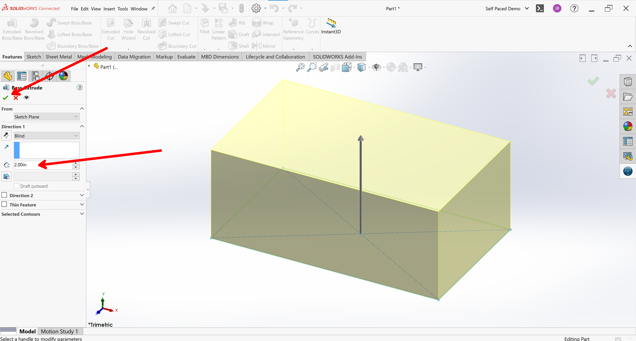
There you have it! Your first SOLIDWORKS part! Once you get the hang of these core capabilities, you can extend into practicing other basic techniques, such as fillets, revolves, sweeps, lofts, and more!
Summary
Part modeling is at the core of all SOLIDWORKS designs. It is important to have a good understanding of core functionality such as sketch creation and solid modeling features (extrude, revolve, loft, sweep, etc). Once you have mastered these capabilities, you can extend into other specialized part modeling tools such as surfacing, sheet metal, structure systems/weldments, and more! If you are looking to accelerate your learning, the SOLIDWORKS Essentials training can get you up to speed with the basics in no time!
Matt is a Customer Success Manager at SWYFT Solutions and started using SOLIDWORKS while earning his Bachelor’s in Mechanical Engineering at Grand Valley State University and has been hooked ever since! He now specializes in 3DEXPERIENCE Works solutions, including 3DEXPERIENCE SOLIDWORKS. Outside of work, Matt loves to travel, hike, and discover new music.
Connect with Matt on LinkedIn